Resources: DC Explorer
Data centre systems, from grid to rack
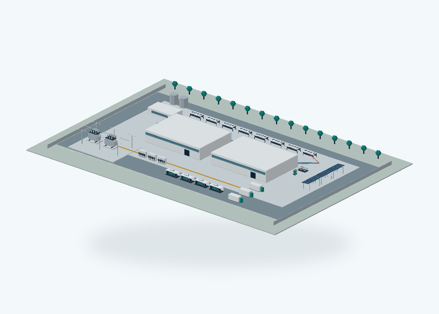
Conceptual 3D models of a campus, a data hall and 17 cooling, electrical and IT components. Select a system to see its purpose, interfaces, buyer questions and sources, then add it to your requirement brief.
Conceptual design, not engineering. Original illustrative geometry. Dimensions, quantities and layout do not establish capacity, compatibility, redundancy, performance, safety, a Tier rating or code compliance. It is not BIM, CFD, a single-line diagram or a digital twin, and no manufacturer has approved it.
Interactive 3D: orbit, cutaways, exploded parts and system paths. Loads about 0.7 MB of code plus the selected model (0.03 to 4 MB).
System archetypes in 2D
Four common arrangements drawn as a 2D system graph with a keyboard-friendly list. They use the same systems as the 3D view and link to the same records. Drafts, not yet engineering-reviewed.
Conventional air-cooled colocation
Servers are cooled by air. Computer room air handlers move heat into a chilled-water or refrigerant system that rejects it outdoors. Typical of multi-tenant halls with mixed, moderate rack densities.
16 systems, 15 connections
Mixed air and direct liquid cooling
Cold plates take most heat from processors into a technical liquid loop served by a CDU, while CRAHs remove the residual heat from memory, drives, power supplies and the room.
18 systems, 18 connections
Dense AI liquid-cooled cluster
Rack-scale accelerator systems are liquid cooled through CDUs, with warm facility water that allows dry coolers to reject heat for much of the year. Network core and compute often have separate power and availability strategies.
20 systems, 21 connections
Brownfield liquid-cooling retrofit
An operating air-cooled hall adds liquid-cooled racks. CDUs connect either to the existing chilled-water system or reject heat to room air, within the limits of the existing electrical, structural and plant capacity.
18 systems, 19 connections
System list
The same systems as the 3D view, as plain HTML. Works without WebGL and with a keyboard or screen reader. Each item opens in 3D with a stable link.
Campus
The connected campus
Explore the electrical, thermal and IT systems that make a data centre work. Select a system to inspect its equipment and procurement questions.
Interfaces: Utility electricity, Facility cooling loops, IT and network loads
Buyer checks (3)
- Which capacity is IT, facility or grid power?
- What is commissioned versus ultimate design capacity?
- Which systems need continuity and for how long?
Parts (6)
- Compute halls: An illustrative building envelope around IT equipment and service spaces.
- Heat rejection: Outdoor equipment rejects heat from facility cooling loops.
- Grid interface: Illustrative substation and transformer equipment.
- Standby generation: An alternate electrical source; no runtime or reliability is implied.
- Energy storage: Power and usable energy need separate specifications.
- On-site solar: Illustrative renewable generation, not a firm supply claim.
On CoolPower Index: Data centre power distribution, Heat rejection, Capacity definitions: IT, facility, grid and thermal MW
Technical references (explain functions, do not validate this geometry): DOE / FEMP: data-centre design guidance (opens in a new tab), NVIDIA: facilities system relationships (opens in a new tab)
Open in 3D: The connected campusOriginal conceptual geometry. Model file 3.7 MB.
Inside the data hall
See rack rows, cooling distribution, overhead services and a network core. Open the roof or isolate an equipment family.
Interfaces: Rack power, Facility and technology cooling loops, Network fabric
Buyer checks (3)
- What heat remains in air after liquid capture?
- Are floor load and maintenance clearances adequate?
- How will flushing, water quality and commissioning be managed?
Parts (5)
- Building envelope: The cutaway is for orientation; dimensions and clearances are illustrative.
- Compute rows: Generic racks, with no implied rack count or electrical capacity for a real project.
- Liquid services: CDUs and manifolds serve a separate technology cooling loop.
- Residual-air cooling: Air-cooled loads still need a defined thermal path.
- Overhead distribution: Simplified busway and cable services; not an electrical single-line.
On CoolPower Index: Direct liquid cooling (direct-to-chip), Data centre power distribution, Capacity definitions: IT, facility, grid and thermal MW, Cooling technology selection guide
Technical references (explain functions, do not validate this geometry): DOE / FEMP: data-centre design guidance (opens in a new tab), NVIDIA: facilities system relationships (opens in a new tab)
Open in 3D: Inside the data hallOriginal conceptual geometry. Model file 1.1 MB.
Cooling
Coolant distribution unit
A CDU separates the facility-water circuit from the technology cooling circuit. Inspect the exchanger, pumps, filters and controls.
Interfaces: Facility-water supply / return, Technology-loop supply / return, Electrical supply and controls
Buyer checks (3)
- Capacity at which approach temperature and fluid?
- Required flow, differential pressure and filtration?
- Duty/standby strategy, service access and control integration?
Parts (6)
- Enclosure: Protective frame and removable access panels.
- Heat exchanger: Transfers heat between separate fluid circuits.
- Pump set: Provides the specified flow and pressure; redundancy is a project choice.
- Filtration: Fluid cleanliness must meet the selected equipment requirements.
- Circuit connections: Facility and technology loops remain hydraulically separate.
- Controls and sensors: Monitor temperature, pressure, flow and alarms.
On CoolPower Index: CDUs & Direct Liquid Cooling suppliers, Coolant distribution units (CDUs), Direct liquid cooling (direct-to-chip), CDU comparison guide, Cooling and power RFI checklist
Technical references (explain functions, do not validate this geometry): DOE / FEMP: data-centre design guidance (opens in a new tab), DOE / FEMP: cooling and water efficiency (opens in a new tab)
Open in 3D: Coolant distribution unitOriginal conceptual geometry. Model file 79 kB.
Dry cooler
Fans move ambient air across a finned coil to reject heat from a closed fluid circuit. Performance depends on ambient and fluid conditions.
Interfaces: Warm fluid in, Cooler fluid out, Electrical power / controls
Buyer checks (3)
- Which design ambient and fluid temperatures?
- Sound limit, approach temperature and fan power?
- Glycol, freeze protection and maintenance access?
Parts (5)
- Support frame: Raises and supports the illustrative coil bank.
- Finned coils: Transfer heat from fluid to outdoor air.
- Axial fans: Move air through the heat-exchange surfaces.
- Headers and connections: Distribute fluid across the coil circuits.
- Fan guards: Illustrative guards and access boundaries.
On CoolPower Index: Heat Rejection suppliers, Heat rejection, Cooling and power RFI checklist
Technical references (explain functions, do not validate this geometry): DOE / FEMP: cooling and water efficiency (opens in a new tab), NVIDIA: facilities system relationships (opens in a new tab)
Open in 3D: Dry coolerOriginal conceptual geometry. Model file 96 kB.
CRAH / fan-wall unit
A computer-room air handler transfers heat from room air to a chilled-fluid circuit. It is distinct from the chiller or outdoor heat-rejection plant.
Interfaces: Room-air return / supply, Cooling-fluid supply / return, Electrical supply and controls
Buyer checks (3)
- Sensible duty at the actual entering-air and fluid conditions?
- Airflow, external static pressure and fan power?
- Condensation, humidity control, filtration and service access?
Parts (5)
- Enclosure: Illustrative access panels and support frame.
- Cooling coil: Transfers room-air heat into the fluid circuit.
- Fan array: Moves room air through the coil and unit.
- Air filters: Protect the equipment and air path.
- Fluid and control interfaces: Fluid supply/return and local controls.
On CoolPower Index: Chillers & Precision Cooling suppliers, Cooling technology selection guide
Technical references (explain functions, do not validate this geometry): DOE / FEMP: data-centre design guidance (opens in a new tab), DOE / FEMP: cooling and water efficiency (opens in a new tab)
Open in 3D: CRAH / fan-wall unitOriginal conceptual geometry. Model file 79 kB.
Air-cooled chiller
A refrigerant cycle removes heat from a chilled-fluid circuit. The outdoor condenser rejects that heat plus compressor input.
Interfaces: Chilled fluid supply / return, Outdoor air, Electrical supply
Buyer checks (3)
- Duty at the actual ambient and leaving-water temperature?
- Part-load efficiency and low-load behavior?
- Refrigerant, sound, water quality and redundancy?
Parts (6)
- Base and structure: Illustrative modular equipment frame.
- Evaporator: Transfers heat from the chilled-fluid circuit to refrigerant.
- Compressors: Provide the work needed by the refrigeration cycle.
- Condenser coils: Reject heat to ambient air.
- Condenser fans: Move air over condenser surfaces.
- Electrical and controls: Operate the equipment and report faults.
On CoolPower Index: Chillers & Precision Cooling suppliers, Heat rejection, Cooling technology selection guide
Technical references (explain functions, do not validate this geometry): DOE / FEMP: data-centre design guidance (opens in a new tab), DOE / FEMP: cooling and water efficiency (opens in a new tab)
Open in 3D: Air-cooled chillerOriginal conceptual geometry. Model file 113 kB.
Cooling tower
An open tower rejects heat using evaporation and air movement. Water treatment, makeup and blowdown are part of the system.
Interfaces: Warm circulating water, Makeup / blowdown, Air / electrical power
Buyer checks (3)
- Water availability and consumption limits?
- Wet-bulb conditions, plume and sound requirements?
- Treatment, hygiene and maintenance responsibilities?
Parts (5)
- Cold-water basin: Collects circulating water.
- Fill pack: Promotes contact between air and water.
- Water distribution: Distributes warm circulating water.
- Fan and discharge: Moves air through the tower.
- Casing and louvers: Direct airflow and provide the enclosure.
On CoolPower Index: Heat Rejection suppliers, Heat rejection
Technical references (explain functions, do not validate this geometry): DOE / FEMP: cooling and water efficiency (opens in a new tab)
Open in 3D: Cooling towerOriginal conceptual geometry. Model file 50 kB.
Pump and filtration skid
A generic distribution skid illustrates pumps, valves, filters and a common header. Duty and standby arrangements require hydraulic design.
Interfaces: System supply / return, Electrical supply, Controls
Buyer checks (3)
- Design flow and head across the operating envelope?
- Fluid properties and pump material compatibility?
- Isolation, standby logic and maintenance access?
Parts (6)
- Skid base: Supports the mounted assembly.
- Pump assemblies: Illustrative motors and centrifugal pump casings.
- Headers: Connect the pump branches to the system.
- Isolation valves: Allow isolation and maintenance.
- Strainers: Provide a conceptual filtration location.
- Control panel: Local instrumentation and control enclosure.
On CoolPower Index: Warm-water cooling loops
Technical references (explain functions, do not validate this geometry): DOE / FEMP: data-centre design guidance (opens in a new tab), DOE / FEMP: cooling and water efficiency (opens in a new tab)
Open in 3D: Pump and filtration skidOriginal conceptual geometry. Model file 39 kB.
Plate heat exchanger
A plate exchanger transfers heat between two isolated circuits. Plate geometry, fluids and approach conditions determine actual performance.
Interfaces: Primary fluid circuit, Secondary fluid circuit
Buyer checks (3)
- Thermal duty and approach temperatures?
- Fluid chemistry, fouling and pressure limits?
- Gasket/material compatibility and service strategy?
Parts (4)
- Fixed and moving frames: Compress the plate pack.
- Plate pack: Alternating channels transfer heat between fluids.
- Tie bars: Maintain assembly compression.
- Circuit ports: Separate inlet and outlet connections for two circuits.
On CoolPower Index: Warm-water cooling loops, Data centre heat reuse
Technical references (explain functions, do not validate this geometry): DOE / FEMP: cooling and water efficiency (opens in a new tab)
Open in 3D: Plate heat exchangerOriginal conceptual geometry. Model file 43 kB.
Server cold plate
An original cutaway of a generic cold plate shows the lid, flow passages and thermal contact base. It is not a representation of a commercial product.
Interfaces: Device thermal interface, Technology-loop fluid
Buyer checks (3)
- What device and mounting envelope?
- Heat flux, pressure drop and allowable temperatures?
- Material, coolant and leak-test compatibility?
Parts (5)
- Top cover: Seals the fluid cavity.
- Flow channels: Illustrative internal passages, not a validated hydraulic geometry.
- Thermal base: Conducts heat from the device interface.
- Fluid ports: Connect the cold plate to the technology loop.
- Mounting features: Illustrative attachment points; no fit claim.
On CoolPower Index: CDUs & Direct Liquid Cooling suppliers, Direct liquid cooling (direct-to-chip), Cooling technology selection guide
Technical references (explain functions, do not validate this geometry): NVIDIA: rack-scale hardware example (opens in a new tab), DOE / FEMP: cooling and water efficiency (opens in a new tab)
Open in 3D: Server cold plateOriginal conceptual geometry. Model file 32 kB.
Electrical
Power transformer
A generic oil-filled transformer model exposes the tank, cooling banks and bushings. Ratings, protection and fire provisions are project specific.
Interfaces: Higher-voltage connection, Lower-voltage connection, Protection / monitoring
Buyer checks (3)
- MVA, voltage ratio, impedance and loss basis?
- Fault level, protection and earthing scheme?
- Cooling, fire separation and delivery constraints?
Parts (5)
- Main tank: Contains the active assembly in this conceptual oil-filled example.
- Radiator banks: Transfer losses from the tank fluid to air.
- Bushings: Insulated electrical interfaces.
- Conservator / auxiliaries: Illustrative auxiliary tank and pipework.
- Foundation and base: Illustrative support; not a civil design.
On CoolPower Index: Switchgear & Transformers suppliers, Data centre power distribution
Technical references (explain functions, do not validate this geometry): DOE / FEMP: data-centre design guidance (opens in a new tab), NVIDIA: facilities system relationships (opens in a new tab)
Open in 3D: Power transformerOriginal conceptual geometry. Model file 104 kB.
MV / LV switchgear
An illustrative lineup of switchgear cubicles shows incoming, protection and outgoing sections. It is not a certified assembly or single-line design.
Interfaces: Incoming supply, Outgoing feeders, Protection / controls
Buyer checks (3)
- Voltage, current and fault-withstand ratings?
- Protection coordination, arc classification and earthing?
- Maintainability, segregation and access?
Parts (5)
- Cubicle structure: Metal-enclosed modular lineup.
- Breaker compartments: Illustrative removable breaker modules.
- Busbar zone: Represents the internal distribution path.
- Protection and metering: Front-panel protection and status devices.
- Cable interfaces: Conceptual termination space.
On CoolPower Index: Switchgear & Transformers suppliers, Data centre power distribution
Technical references (explain functions, do not validate this geometry): DOE / FEMP: data-centre design guidance (opens in a new tab), NVIDIA: facilities system relationships (opens in a new tab)
Open in 3D: MV / LV switchgearOriginal conceptual geometry. Model file 80 kB.
UPS and battery system
A modular UPS with a separate battery cabinet illustrates conversion, bypass and stored energy. Runtime depends on load, usable energy and conditions.
Interfaces: AC input / bypass, Protected output, Battery DC / controls
Buyer checks (3)
- Which loads need UPS continuity?
- Usable runtime at end of life and actual load?
- Bypass, redundancy, harmonics and maintenance strategy?
Parts (5)
- UPS enclosure: Houses modular conversion equipment.
- Power modules: Illustrative conversion modules.
- Bypass section: A conceptual alternate power path.
- Battery cabinet: Stored energy is distinct from UPS power rating.
- Controls and display: Local monitoring and alarms.
On CoolPower Index: UPS & Power Distribution suppliers, Backup power and energy storage, Data centre power distribution, Cooling and power RFI checklist
Technical references (explain functions, do not validate this geometry): DOE / FEMP: data-centre design guidance (opens in a new tab), NVIDIA: facilities system relationships (opens in a new tab)
Open in 3D: UPS and battery systemOriginal conceptual geometry. Model file 66 kB.
Battery energy storage
A containerised BESS shows battery racks, power conversion and thermal management. MW and usable MWh must be specified separately.
Interfaces: Grid / site electrical interface, Control and dispatch, Thermal / safety interfaces
Buyer checks (3)
- Power, usable energy, duration and reserve?
- Efficiency, degradation and end-of-life criteria?
- Siting, safety, grid connection and dispatch obligations?
Parts (5)
- Container and structure: Illustrative outdoor enclosure.
- Battery racks: Generic cell-module assemblies.
- Power conversion: AC/DC interface, controls and conversion equipment.
- Thermal management: Maintains the battery operating environment.
- Safety provisions: Conceptual detection and isolation; not a safety design.
On CoolPower Index: BESS & Energy Storage suppliers, Backup power and energy storage
Technical references (explain functions, do not validate this geometry): DOE: microgrids and large electrical loads (opens in a new tab), NVIDIA: facilities system relationships (opens in a new tab)
Open in 3D: Battery energy storageOriginal conceptual geometry. Model file 187 kB.
Standby generator set
A generic engine-generator assembly includes the engine, alternator, radiator and exhaust. Duty rating and fuel autonomy are not established by this model.
Interfaces: Fuel, Electrical output / switchgear, Air / cooling / exhaust
Buyer checks (3)
- Standby or continuous duty and net output?
- Fuel type, autonomy, emissions and permitted hours?
- Start/step-load performance, noise and maintenance?
Parts (6)
- Base and mounts: Illustrative engine-generator support.
- Engine: Mechanical prime mover.
- Alternator: Converts mechanical power to electrical power.
- Cooling package: Rejects engine heat.
- Exhaust system: Illustrative exhaust and silencer.
- Acoustic enclosure: Illustrative weather/acoustic housing.
On CoolPower Index: Gensets & On-site Power suppliers, Backup power and energy storage
Technical references (explain functions, do not validate this geometry): DOE: microgrids and large electrical loads (opens in a new tab), DOE / FEMP: data-centre design guidance (opens in a new tab)
Open in 3D: Standby generator setOriginal conceptual geometry. Model file 55 kB.
IT & digital
Liquid-cooled IT rack
A generic rack-scale system with server trays, a busbar and liquid manifolds. It is not branded hardware or a validated configuration.
Interfaces: Rack electrical supply, Technology cooling loop, Network fabric
Buyer checks (3)
- Typical, maximum and design power for the exact configuration?
- Liquid-capture fraction and residual-air load?
- Weight, connections, clearances and service strategy?
Parts (5)
- Rack frame: Illustrative equipment enclosure and rails.
- Compute trays: Generic front-access compute trays.
- Power shelves / busbar: Simplified rack-level power distribution.
- Cooling manifolds: Separate supply and return connections.
- Network connections: Illustrative management/network space.
On CoolPower Index: Direct liquid cooling (direct-to-chip), 800 VDC rack power
Technical references (explain functions, do not validate this geometry): NVIDIA: rack-scale hardware example (opens in a new tab), NVIDIA: facilities system relationships (opens in a new tab)
Open in 3D: Liquid-cooled IT rackOriginal conceptual geometry. Model file 106 kB.
GPU server tray
A generic server-tray cutaway reveals processors, cold plates, memory, fans and interface connections. Chip count and arrangement are illustrative.
Interfaces: Electrical supply, Liquid supply / return, Network / management
Buyer checks (3)
- Exact configuration and qualified power envelope?
- Fluid, temperatures, pressure drop and connectors?
- What fraction of heat remains in air?
Parts (6)
- Tray chassis: Illustrative sliding enclosure.
- System board: A generic board, not a commercial layout.
- Compute devices: Illustrative processor packages.
- Cold plates and tubing: Transfers device heat into a liquid circuit.
- Memory / storage: Illustrative supporting devices.
- Residual-air fans: Move air across components outside the liquid-cooled path.
On CoolPower Index: Direct liquid cooling (direct-to-chip)
Technical references (explain functions, do not validate this geometry): NVIDIA: rack-scale hardware example (opens in a new tab)
Open in 3D: GPU server trayOriginal conceptual geometry. Model file 98 kB.
Network switch
A generic switch model highlights ports, electronics, power modules and fans. Network capacity and interoperability need actual product evidence.
Interfaces: Data links / optics, Electrical supply, Management / air
Buyer checks (3)
- Required fabric, topology, link speed and optics?
- Power/cooling under the selected port configuration?
- Resilience, firmware and interoperability evidence?
Parts (5)
- Chassis: Rack-mount form factor shown for orientation.
- Front-panel interfaces: Illustrative port cages and connectors.
- Switch electronics: Generic switching electronics and heat sinks.
- Power supplies: Illustrative removable supply modules.
- Fan modules: Provide residual-air cooling.
On CoolPower Index: No verified portal record linked yet.
Technical references (explain functions, do not validate this geometry): NVIDIA: rack-scale hardware example (opens in a new tab)
Open in 3D: Network switchOriginal conceptual geometry. Model file 126 kB.
Energy
On-site solar array
A simple solar canopy shows module strings, supports and an inverter. It illustrates a supply option, not a promise of firm data-centre power.
Interfaces: Solar resource, DC collection, AC site connection
Buyer checks (3)
- Resource profile, land/roof area and actual yield?
- Physical connection, curtailment and permitting?
- How will the facility obtain firm supply when generation is low?
Parts (4)
- Support structure: Illustrative steel support and foundations.
- PV modules: Generic modules; output depends on resource and installation.
- Inverter / isolation: Conceptual electrical interface.
- DC collection: Illustrative string collection route.
On CoolPower Index: No verified portal record linked yet.
Technical references (explain functions, do not validate this geometry): DOE: microgrids and large electrical loads (opens in a new tab)
Open in 3D: On-site solar arrayOriginal conceptual geometry. Model file 127 kB.
Engineering pack: size, heat and flow
Extends the planning scenario with CDU counts, loop flow and chiller heat balance. It starts from the scenario you saved in the 3D explorer, and both are kept in the same brief. Every figure is arithmetic on your inputs, not quoted equipment performance or a professional design. A blank or out-of-range input shows as missing, never as zero.
Loading the engineering pack…
What these numbers do and do not tell you
- Nearly all IT electricity becomes heat at the IT boundary. CDU duty, total cooling duty and outdoor heat rejection are different capacities.
- A chiller condenser rejects the evaporator heat plus the compressor input. Pump heat, UPS losses and other loads need their own treatment.
- Flow follows heat = mass flow × specific heat × temperature rise. Use properties for your actual fluid, concentration and temperature (for example from the NIST Chemistry WebBook (opens in a new tab)).
- MW does not establish land, white space, rack weight, floor loading, service clearance or a Tier rating.
- An N+1 count is not proof of concurrent maintainability, failover performance or certification.
- Heat recovery needs a useful temperature, seasonal offtake and distance, often with heat-pump input. Captured heat is not automatically saleable heat.
Context: U.S. DOE FEMP design best practices (opens in a new tab).
Scenario calculator: what it does and does not do
The calculator inside the 3D explorer is arithmetic on your own assumptions. Your inputs are kept with your requirement brief in this browser.
- Annual facility energy (GWh) = design IT MW × average load × assumed annual PUE × 8.76.
- Liquid IT duty (MW) = design IT MW × liquid capture share. Residual IT heat to air (MW) = design IT MW × (1 − liquid capture share).
- Indicative rack count = design IT MW × 1000 ÷ assumed average kW per rack, rounded up.
Annual PUE is not a peak electrical sizing factor. Heat figures cover IT heat only, not other electrical loads or cooling plant input. The rack count ignores mixed populations and non-compute racks. The 3D geometry does not change with the inputs. This is not plant selection, a budget or a reported figure for any real campus.
Sponsorship never changes a model, its technical explanation, the order of systems or which suppliers are listed.
Links to suppliers and known gaps
Generic models link only to existing CoolPower Index categories, technologies and guides (mapping reviewed 18 Oct 2026). Supplier lists come from category pages, which list suppliers with public evidence in that category. A link never means a supplier's product matches or is compatible with a model.
- Pump and filtration skid: No pump or filtration skid supplier category exists yet, so no supplier list is linked.
- Plate heat exchanger: No plate heat exchanger supplier category exists yet, so no supplier list is linked.
- Liquid-cooled IT rack: No IT rack or rack power supplier category exists yet (planned under IT equipment).
- GPU server tray: No server or accelerator supplier category exists yet (planned under IT equipment).
- Network switch: No network equipment category, technology or resource record exists yet.
- On-site solar array: No on-site solar category or technology record exists. The Gensets and on-site power category covers generator sets, fuel cells and temporary power, not solar, so it is not linked.
- CRAH / fan-wall unit: No dedicated air-side cooling technology record exists; linked to the Chillers and precision cooling category only.
- The connected campus: Generic campus layout. Not linked to any tracked project because the geometry is conceptual.
- Inside the data hall: Generic data hall. Not linked to any tracked project because the geometry is conceptual.
Credits and licences
Models, posters and explorer code: original CoolPower Index conceptual library, MIT licence (licence). 3D rendering uses Three.js, MIT licence (notice). Technical references from the U.S. Department of Energy and NVIDIA explain system functions only and do not imply endorsement. See also all credits.